Si-Flux by Fluidverse · Siphonic Innovators since 1983
When it rains, the roof empties.
Full-bore drainage for large roofs — anti-block finless outlets, fewer
downpipes, no gradient. Four decades of siphonic engineering, tested to EN 1253-2.
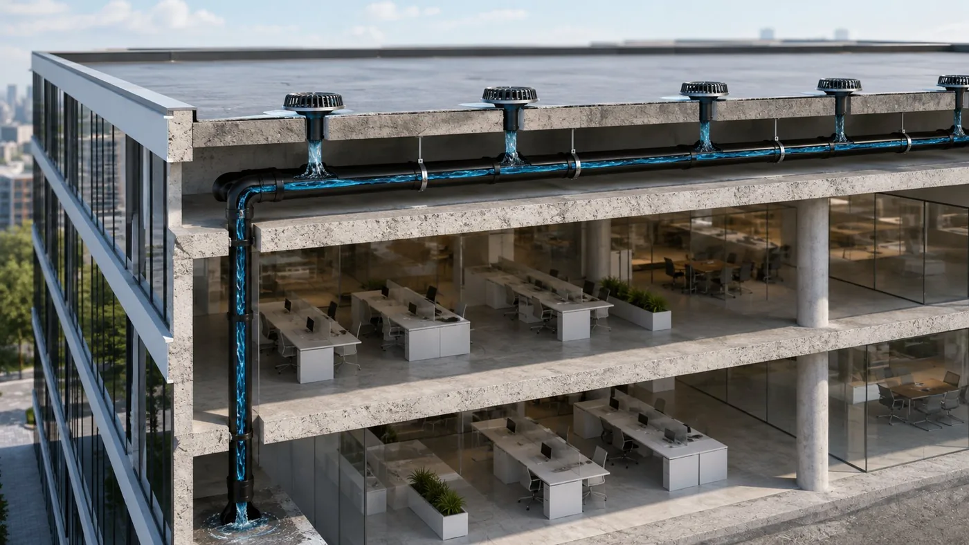
The outlet's geometry stops air being drawn into the system.
The pipework fills completely, negative pressure develops, and the roof is drained at high velocity through a
fraction of the pipework a gravity system would need.
Simplified schematic — outlet quantities, pipe sizing and system layout are calculated
per roof area and rainfall intensity.
Why Siphonic
Less pipe. More building.
Conventional gravity drainage runs part-full, needs falls on
every horizontal run and a downpipe every few metres. Siphonic removes those constraints — which changes
what the architect can do with the building.
Fewer downpipesLarge roof areas drained through far fewer stacks, freeing
façades and floor space.
No gradient neededHorizontal pipework runs level at high level — no falls
eating into ceiling voids.
Smaller pipe diametersFull-bore flow moves more water through less
pipe.
Less underground drainageFewer connection points means a simpler, shorter
below-ground network.
Self-cleansing velocityHigh flow velocity helps keep the system clear in
operation.
System visualisation
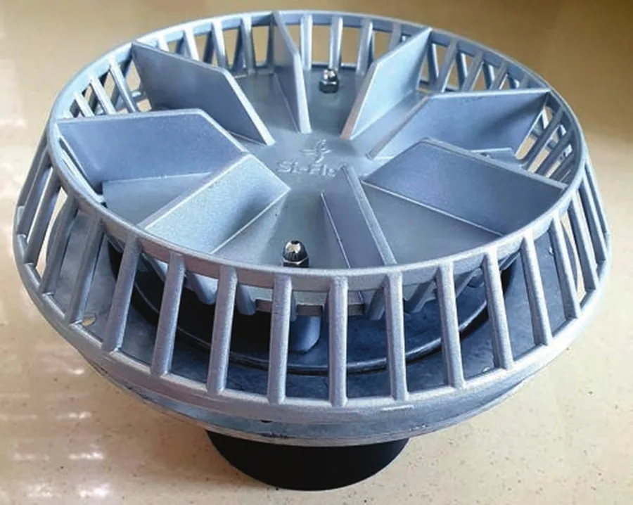
Product visualisation
The Outlet
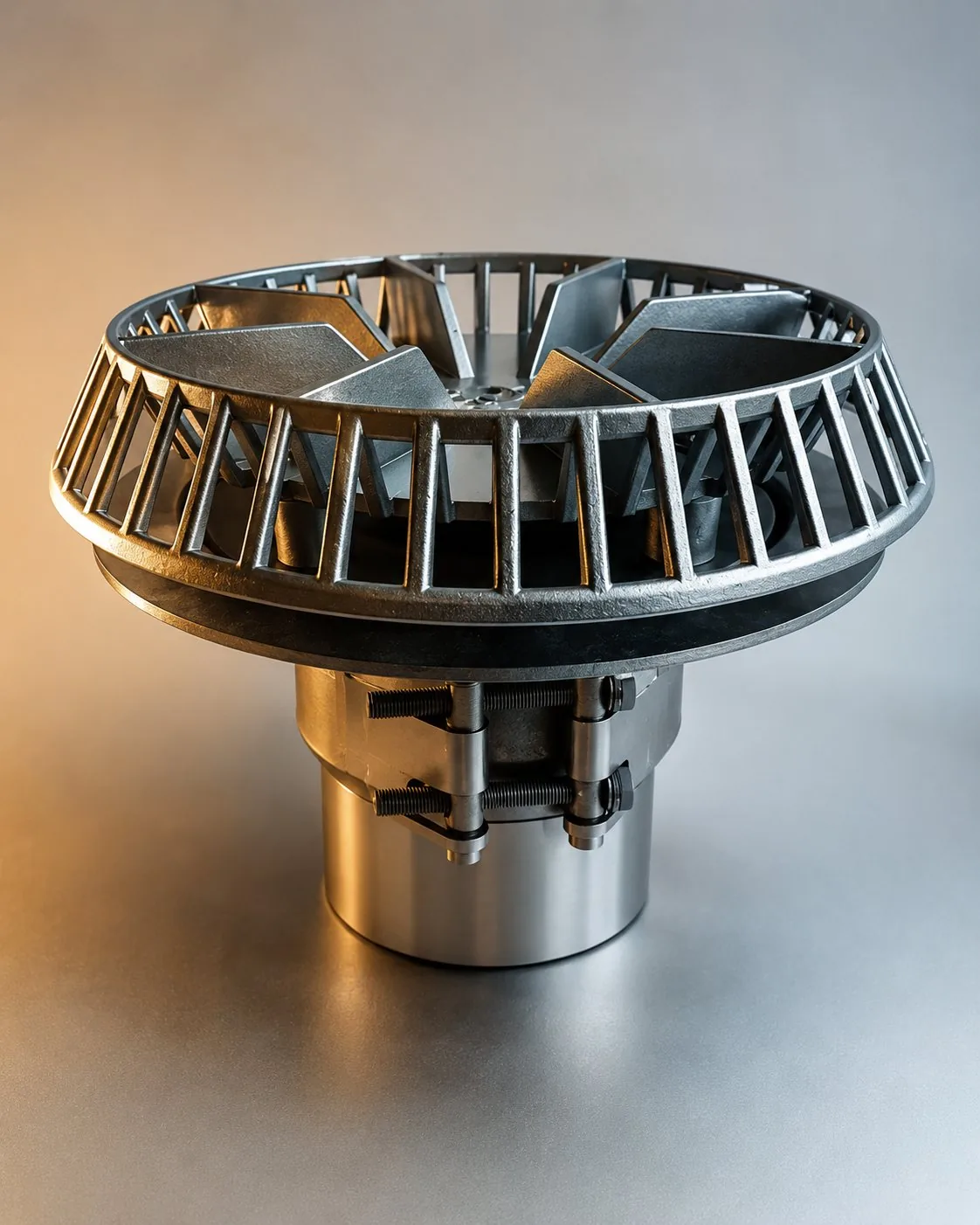
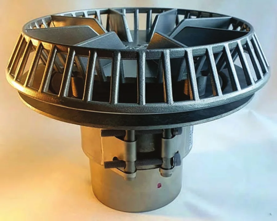
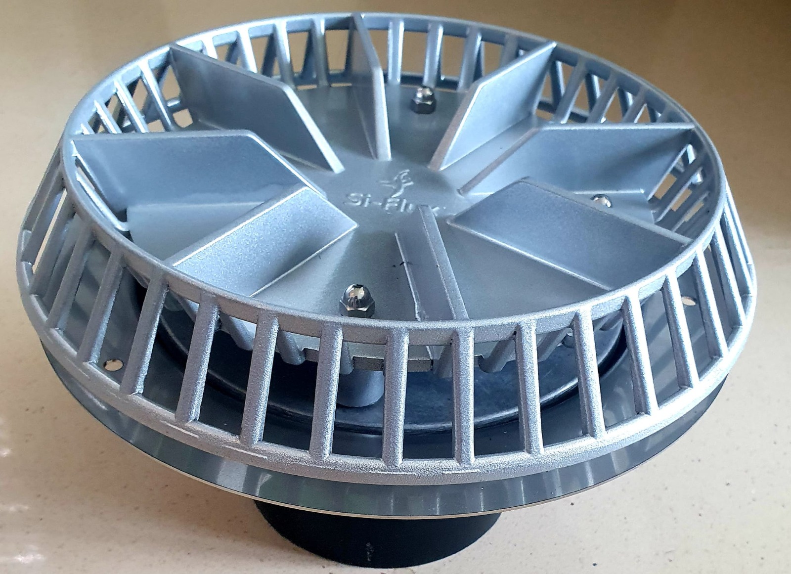
No fins. No baffles. No blockages.
Conventional siphonic outlets use fins or baffle plates to
exclude air — and those same fins catch leaves, plastic bags, sand and silt. Our outlet achieves vortex-free
full-bore flow through geometry alone, with no fin or baffle arrangement to block.
Geometric anti-vortex designFull-bore flow without fins or baffles —
developed as an obstruction-resistant alternative.
Anti-block, provenUKAS-calibrated sand & silt tests show no loss of
discharge as sand depth doubles; operates with debris and plastic bags present.
Built-in membrane clampingEN-approved clamping mechanism — no bolt-on
accessories required.
Class H foot-trafficableMetallic H10 crushproof anti-vortex plate —
passed 1.5 kN load test to EN 1253-2:2003.
Hot work certifiedSubmerged in bitumen at 220 °C for 5 minutes with no
visible distress — suitable for hot-applied roof sealants.
The outlet range
Three bodies, one geometry — selected by pipe material
and roof build.
AL-MP-01
Alloy Body — Metal Pipe
LM6 alloy body for metal pipe applications: cast-iron pipe to EN 877, stainless steel or similar approved
systems.
SS-HD-02
Stainless Body — HDPE
Stainless steel body for HDPE pipe applications, with easy fusion connection to the pipework.
AL-HD-03
Alloy Body — HDPE
LM6 alloy body for HDPE pipe applications — the lightweight alloy alternative for fusion-jointed systems.
Parameter
AL-MP-01
SS-HD-02
AL-HD-03
Body material
LM6 Alloy
Stainless Steel
LM6 Alloy
Pipe application
Metal pipe — CI to EN 877, S/S
HDPE
HDPE
Connection
Mechanical / approved coupling
Fusion connection
Fusion connection
Tested flow range
4 – 90 L/s (single outlet)
Cover plate
Metallic H10 crushproof anti-vortex plate — Class H foot trafficable
Membrane clamping
Built-in, tested to EN 1253-2:2003
Hot work application
Certified, tested to EN 1253-2:2003
Warranty
Minimum 10 years, all-metallic outlet
Certificate of origin
UK (Alloy)
Australia (Stainless)
UK (Alloy)
Full test data and technical submittals available on request. Outlet selection,
quantities and pipe sizing are calculated per project.
Roof Build
One outlet family, three roof types.
Membrane Roofs
Built-in clamping mechanism seals directly to the waterproofing membrane — no additional bolt-on
accessories.
Metal Gutters
Outlet arrangement suited to metal gutter and profiled roof systems.
Concrete Roofs
Detailed for concrete roof construction with the appropriate clamping and sealing arrangement.
Certification & Testing
Specify with evidence.
Independently tested and certified — with full test
documentation available for submittal at specification stage.
EN 1253-2:2003
Outlet tested for membrane clamping system, Class H foot-trafficable loading and hot work roof application.
UKAS Calibrated Testing
Anti-block sand & silt and flow tests up to 90 L/s, using UKAS-calibrated apparatus.
University of Sheffield
Rigorously tested by the Department of Civil & Structural Engineering; analytical design programme
developed in collaboration.
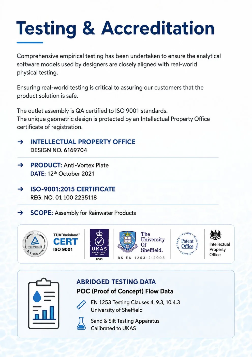
ISO 9001:2015 · TÜV Rheinland 01 100 2235118IPO Design Registration No. 6169704UKAS Calibration 0508 · Mag-Flow 6746Certificate of Origin · UK & Australia
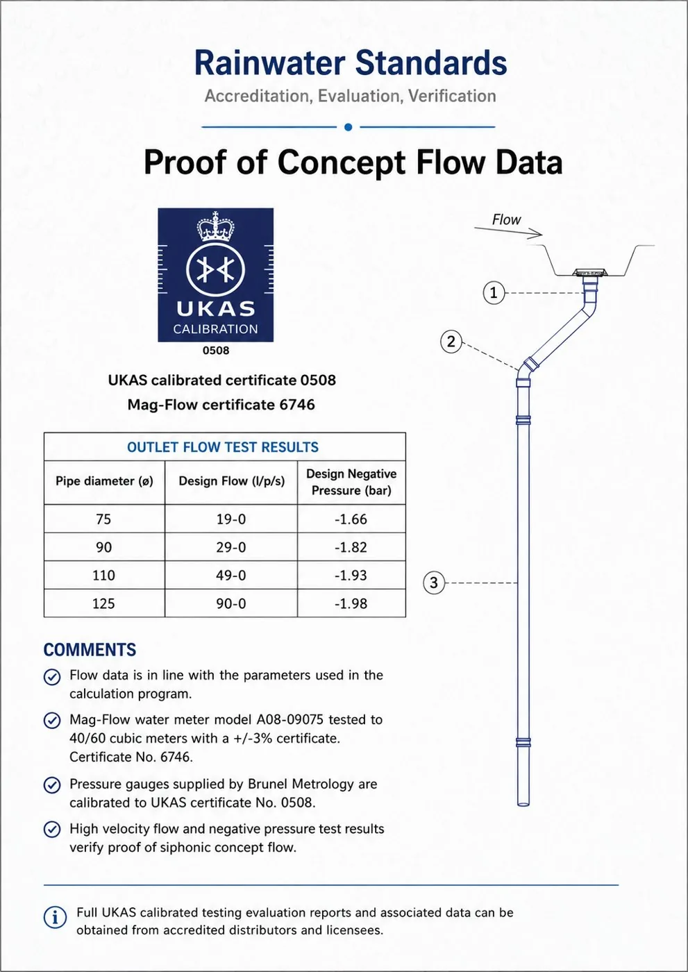
Proof of concept flow data
Outlet flow test results — verified against UKAS-calibrated
instrumentation.
Pipe diameter (ø)
Design flow (L/s)
Design negative pressure (bar)
75
19.0
−1.66
90
29.0
−1.82
110
49.0
−1.93
125
90.0
−1.98
Flow data is in line with the parameters used in the calculation programme.
High-velocity flow and negative pressure results verify proof of siphonic concept flow.
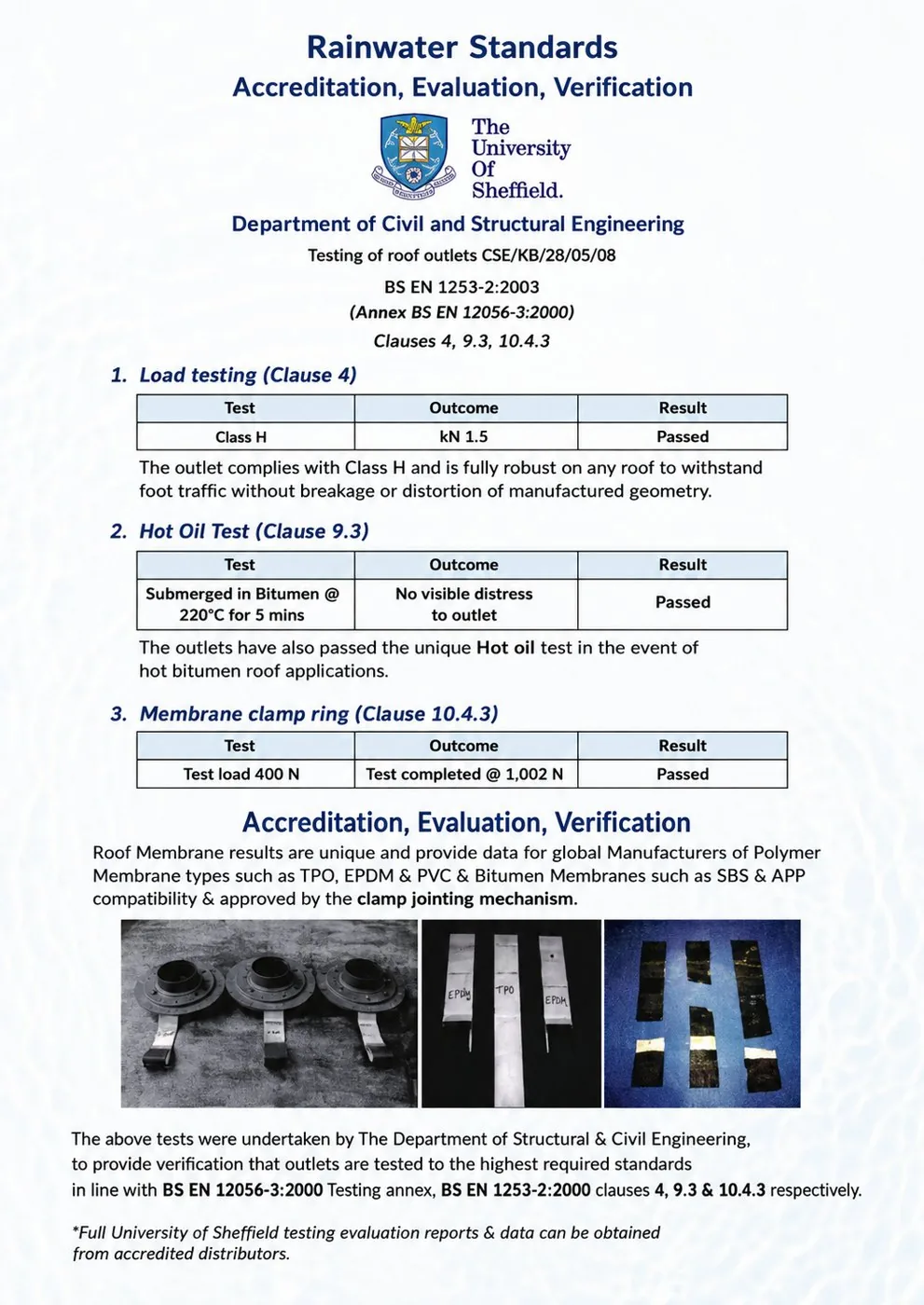
EN 1253-2:2003 test results
Tested by the University of Sheffield, Department of Civil &
Structural Engineering.
Test
Requirement
Outcome
Result
Load testing — Clause 4
Class H
1.5 kN
Passed
Hot oil test — Clause 9.3
Bitumen @ 220 °C, 5 min
No visible distress
Passed
Membrane clamp ring — Clause 10.4.3
Test load 400 N
Completed @ 1,002 N
Passed
Membrane clamping verified compatible with TPO, EPDM, PVC and bitumen membranes
including SBS & APP.
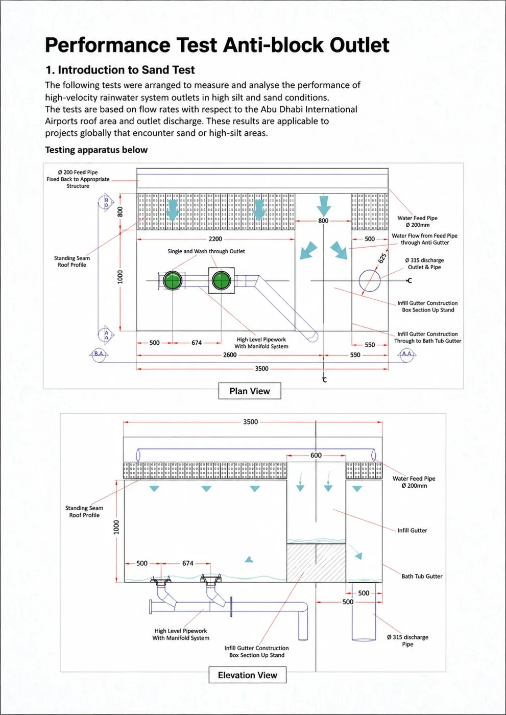
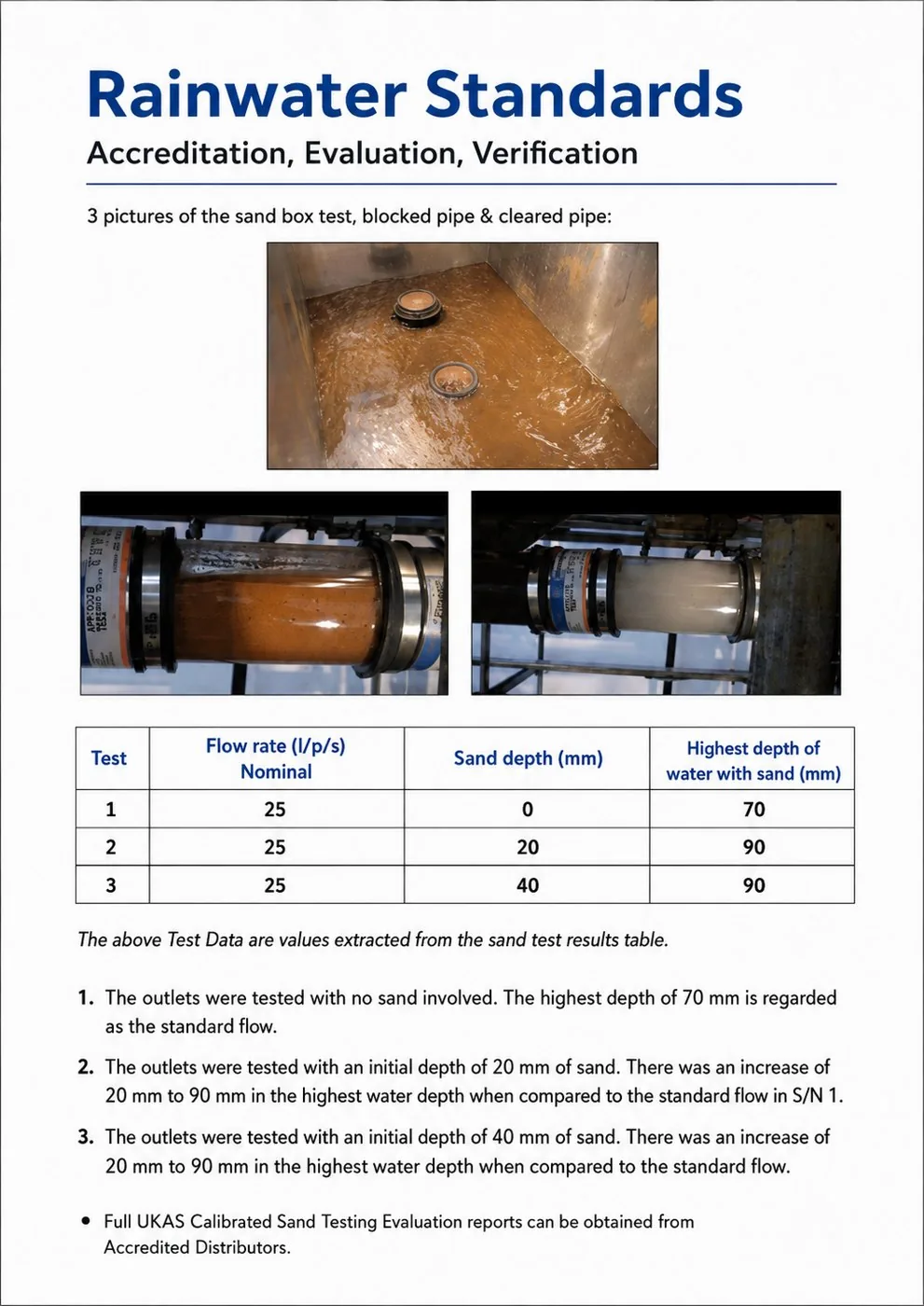
Anti-block sand test
Based on flow rates referenced to Abu Dhabi International
Airport roof area and outlet discharge — applicable to sand and high-silt regions.
Test
Flow rate (L/s)
Sand depth (mm)
Highest water depth (mm)
1
25
0
70
2
25
20
90
3
25
40
90
Doubling sand depth from 20 mm to 40 mm produced no further rise in water depth — the
outlet continues to discharge in silt-laden conditions.
Test & accreditation documents
Click any document to view full size.
Testing & Accreditation ISO 9001 · IPO Design 6169704Proof of Concept Flow Data UKAS 0508 · Mag-Flow 6746University of Sheffield BS EN 1253-2:2003Anti-Block Sand Test Test apparatusSand Test Results Blocked vs cleared pipe
Full UKAS-calibrated testing evaluation reports and University of Sheffield data
available on request. Certification held by Si-Flux, a Fluidverse company.
The Complete Cycle
From the roof to the water table.
Siphonic drainage empties the roof fast. Our stormwater
modules take that water and put it to work — attenuating peak discharge, recharging groundwater or storing it
for reuse. One supplier, one continuous system.
Siphonic drainage earns its place where roof areas are large,
downpipe positions are constrained, or the building simply cannot accommodate conventional falls.
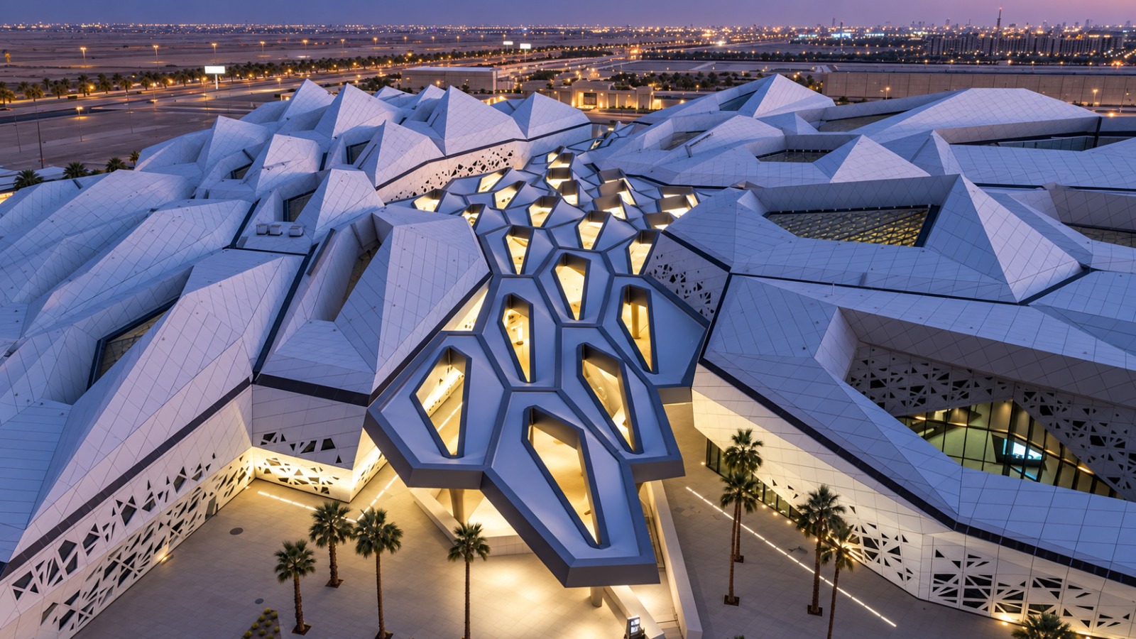
KAPSARC in Riyadh is
the kind of roof siphonic exists for — a honeycomb geometry of interlocking cells, where conventional falls
and downpipe positions would have fought the architecture. Drained on Si-Flux outlets.
Systems built on this outlet technology are installed on
projects worldwide — including Maldives Airport, data centres in Malaysia, and developments across Australia,
Saudi Arabia, Qatar, India and the United Kingdom.
Pipework & Installation
The system doesn't end at the outlet.
Siphonic systems run at full bore under negative pressure —
so the pipework, jointing and bracketry are part of the engineering, not an afterthought. We supply the
complete system.
HDPE pipe & fittingsS12.5 code pipe and fittings, sized from the
hydraulic calculation.
Electrofusion & butt weldingFusion jointing for a fully sealed,
negative-pressure-capable system.
Rail & bracket systemsPurpose-made rail and fixing components to
restrain the pipework under load.
Site equipmentElectrofusion and butt welding machines available for
project execution.
AL-MP-01 outlet with pipe connection
Delivery
Calculated, supplied, commissioned.
Siphonic systems are engineered, not assembled — every layout
is calculated around roof area, rainfall intensity and discharge points.
01Assess
Roof geometry, rainfall design criteria and discharge points.
02Calculate
Outlet quantity, pipe sizing and hydraulic balance.
03Supply
Outlets, pipework and fixings delivered to programme.
04Install
Site execution coordinated with roofing and MEP.
05Commission
Testing, documentation and handover.
Complete the cycle
Drained from the roof. Stored below the ground.
Siphonic systems discharge fast — our stormwater modules give
that water somewhere to go, for attenuation, recharge or reuse.